Asus P5WDG2-WS: Intel 975X goes to Work
by Gary Key on December 6, 2005 12:05 AM EST- Posted in
- Motherboards
ASUS P5WDG2-WS: Features
The Intel SATA II ports are conveniently located below the ICH7R chipset and above the primary IDE connector. The SATA II ports feature the new clamp and latch design. Asus did not include the new cable designs in their accessory kit, which greatly enhance the security of the SATA connections. However, the Intel SATA II ports are color coded for primary (Red) and secondary (Black) operation when the ports are set to Standard IDE mode.
The Intel 6702PXH chipset is located in between the DIMM module slots and ICH7R chipset. Below the 6702PXH chipset is a 6-pin jumper switch that allows you to set the PCI-X speed settings to Auto, Force 133MHz, and Force 100MHz.
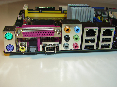
The Marvell 88SE6141 SATA II Raid ports, Intel USB connector, IEEE1394a connector, chassis panel, and Com1 serial port are located along the left edge of the board. The CMOS reset is a traditional jumper design located in-between the BIOS chip and the chassis panel.
The board comes with (2) physical PCI Express x16 slots, (2) PCI-X slots, and (2) PCI 2.2 slots. The layout of this design offers a good balance of slots and allows for numerous add-in peripheral cards. We did have an issue installing our Sound Blaster X-FI and ATI HDTV cards in the first PCI 2.2 slot. The capacitor in front of the optical drive audio connector had to be slightly tweaked towards the second PCI-X slot in order to install the cards. We do have a concern about the placement of this capacitor on a long term basis in the board.
We did not have any issues installing an ATI X850 Crossfire Edition setup in the two x16 PCI Express slots. This configuration will render the first PCI-X slot useless. There were not any issues utilizing this slot with video cards containing single slot cooling systems when utilizing our Areca ARC-1110 SATA II RAID host adapter.
One of the main design features that Asus engineered into this board is an exclusive 8-phase voltage regulator power design that can significantly lower operating temperatures while reducing input ripple current and output ripple voltages . In fact, the input ripple current is over three times lower than a traditional 4-phase design while output ripple voltages are four times lower. The power consumption compared to the 4-phase design is about 10% less while the 8-phase design has the advantage of quicker transient responses and increased dependability due to lower thermal values.
The Northbridge, Southbridge, and PCI-X chipsets are passively cooled with heatsinks that do not interfere with any installed peripherals. In fact, this system kept the chipsets cool enough that additional chipset voltage was not a factor in our overclocking tests. Asus places the eight-pin 12V auxiliary power connector at the top of the CPU socket area, but out of the way of most aftermarket cooling solutions.
The BIOS options are abundant on the Asus P5WDG2-WS, with memory voltage to 2.3V, and an extensive range of chipset, bus, and vCore voltage adjustments. Memory ratios are limited compared to the nForce4 Intel Edition boards, but Asus did manage to offer enough settings to make the board competitive. The board fully supports manual memory timing adjustments or allows for an Auto setting that will set the memory to the SPD settings. You have the ability to overclock the system utilizing the AI Overclock profiles that have preset percentages or to use the AI N.O.S. feature that will dynamically overclock the system based upon system loads.
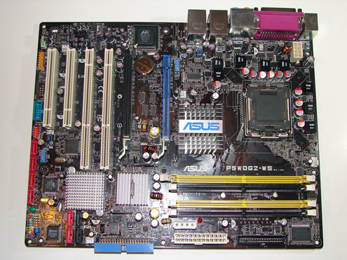
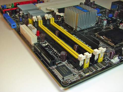
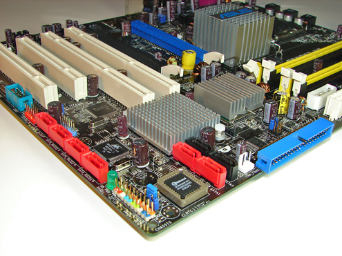
The Intel SATA II ports are conveniently located below the ICH7R chipset and above the primary IDE connector. The SATA II ports feature the new clamp and latch design. Asus did not include the new cable designs in their accessory kit, which greatly enhance the security of the SATA connections. However, the Intel SATA II ports are color coded for primary (Red) and secondary (Black) operation when the ports are set to Standard IDE mode.
The Intel 6702PXH chipset is located in between the DIMM module slots and ICH7R chipset. Below the 6702PXH chipset is a 6-pin jumper switch that allows you to set the PCI-X speed settings to Auto, Force 133MHz, and Force 100MHz.
The Marvell 88SE6141 SATA II Raid ports, Intel USB connector, IEEE1394a connector, chassis panel, and Com1 serial port are located along the left edge of the board. The CMOS reset is a traditional jumper design located in-between the BIOS chip and the chassis panel.
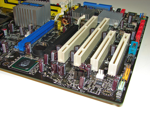
We did not have any issues installing an ATI X850 Crossfire Edition setup in the two x16 PCI Express slots. This configuration will render the first PCI-X slot useless. There were not any issues utilizing this slot with video cards containing single slot cooling systems when utilizing our Areca ARC-1110 SATA II RAID host adapter.
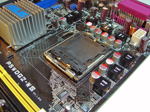
One of the main design features that Asus engineered into this board is an exclusive 8-phase voltage regulator power design that can significantly lower operating temperatures while reducing input ripple current and output ripple voltages . In fact, the input ripple current is over three times lower than a traditional 4-phase design while output ripple voltages are four times lower. The power consumption compared to the 4-phase design is about 10% less while the 8-phase design has the advantage of quicker transient responses and increased dependability due to lower thermal values.
The Northbridge, Southbridge, and PCI-X chipsets are passively cooled with heatsinks that do not interfere with any installed peripherals. In fact, this system kept the chipsets cool enough that additional chipset voltage was not a factor in our overclocking tests. Asus places the eight-pin 12V auxiliary power connector at the top of the CPU socket area, but out of the way of most aftermarket cooling solutions.
The BIOS options are abundant on the Asus P5WDG2-WS, with memory voltage to 2.3V, and an extensive range of chipset, bus, and vCore voltage adjustments. Memory ratios are limited compared to the nForce4 Intel Edition boards, but Asus did manage to offer enough settings to make the board competitive. The board fully supports manual memory timing adjustments or allows for an Auto setting that will set the memory to the SPD settings. You have the ability to overclock the system utilizing the AI Overclock profiles that have preset percentages or to use the AI N.O.S. feature that will dynamically overclock the system based upon system loads.


31 Comments
View All Comments
Gary Key - Tuesday, December 6, 2005 - link
We are still working on a way to properly show this in the graph engine.Thank you.
imaheadcase - Tuesday, December 6, 2005 - link
I saw this article 2 times put up already. anyone else seeing this?Last half a dozen reviews show up, i see people comment on them, then they disappear and come back latter. weird
wilburpan - Monday, December 5, 2005 - link
According to your Ethernet tests:Gigabyte GA-G1975X: 951.4 Mb/s
Asus P5WDG2-WS: 950.3 MB/s
Gigabyte GA-G1975X: 16.04% cpu utilization
Asus P5WDG2-WS: 23.78%
And in your text:
"The Marvell 88E8062 PCI Express Dual LAN solution exhibits slightly higher throughput along with very good CPU utilization rates. The Broadcom 5789KFB option on the Gigabyte board offers excellent throughput, but at a slightly higher CPU utilization than on other solutions."
With the data you have, it seems the exact opposite conclusion should be made.
Gary Key - Tuesday, December 6, 2005 - link
Hi,Unfortunately, our document engine had a mind of its own last night when the article went up the first time as it was not completed yet. The last couple of pages are correct now along with additional information that was not available last night. We had to wait on Asus to provide shipping drivers and Marvell firmware which changed the original scores (went down but stability increased). The new graphs were correct but my text changes had not caught up yet. We have been informed by Asus the 88E8066 chipset will actually be used on the board in the near future.
Thank you.
BrownTown - Tuesday, December 6, 2005 - link
interesting stuff for the Presler there, I eagerly await your new article :pDanDaMan315 - Monday, December 5, 2005 - link
yayVegito - Tuesday, December 6, 2005 - link
Juicy.. I just need these pcix + pcie board for an amd machine.. :)Gary Key - Tuesday, December 6, 2005 - link
We highly suggested this to Asus. ;->Pirks - Tuesday, December 6, 2005 - link
Many many years from now we'll get another Asus or any other r333w1 mobo (DFI LanParty Ultra 3.0? :) with quantum 1000 GHz CPU, UltraWideFirewire 24000, USB 8.0, built in laser keyboard link and wireless 80" display link... and a LOT more... and.......AND...
...and A FLOPPY CONNECTOR!!!
and AN LPT PORT!!!!!
and PS/2 JACKS!!!!!!
AND TWO, LISTEN TO THIS - !TWO! COM PORTS!!!!
bwahahahahahahaaaaa
I just can't look at all the museum artefacts on these so called "professional" mobos, when Macs have only USB and FW as their standard interfaces for years!
Yea I know Mac hardware is sucky/expensive, no cool gaming and stuff, but... I really understand well some of my Mac using buddies when they visit me while I'm working on one of my PC's "professional" mobos (upgrading heatsink or something), and they see one of these huge LPT connectors and they're like "WTF???!?!?"
I know noone cares about this stuff, noone will ever make decent and inexpensive legacy free PC mobo, just wanted to vent it off... thanks :)
Saist - Tuesday, December 6, 2005 - link
obviously you have never tried to run a data center, or ever bought hardware on a budget, nor that you run windows...or are you conviently forgetting that Windows has the worst in-box hardware support available and that to run many SATA drives requires installing drivers as though they are SCISI devices rather than on-chip devices.
Or that not everybody can afford to upgrade to a new laser jet / ink jet / Hp OfficeJet at every new release, and that for many a business the stock dot matrix offers the best price/performance and there is no reason to replace a perfectly functioning dot/matrix printer for something that costs a lot more to run.
or that usb support for keyboards is a little spotty in the Microsoft bootloader if you do try to run multiple versions of windows
Or that many older devices still require the com ports.
Sure, if you are building a brand new computer and have no hardware you ever intend to run again, running a legacy free system is a good idea.
But, when you only have 5% of the market at best...
it just doesn't make sense.
Sorry, but I find the laughter and your comments to be so far off base... I can only sigh and wish I had your budget to spend.